VII.4.4.2 Post-processing of connection loads
For the post-processing of connection loads, the first step of the calculations is always to estimate for
each connection the axial force, the shear force, the torsional moment and the bending moment.
Afterwards the criterion for the connection is calculated (sliding, gapping, insert, rivet...). More
precisely, one calculates the critical connection (node or element) and the associated reserve
factor.
VII.4.4.2.1 Calculation of the different components of connection loads
One explains here how the components of loading (axial and shear forces, torsional and bending
moments) are first calculated for the different connections before the calculation of reserve factors for
a selected criterion.
The parameters used for the calculation of these connection load components are always the first 6
parameters of the connection criterion function:
-
1.
- The name of the load case for which the calculation is done.
-
2.
- The name of a first Group (group1) corresponding generally to a part of the structure to
which the connections are connected (sandwich panel, shell, metallic fitting...).
-
3.
- The name of second Group (group2) of finite element entities corresponding generally
to the modeling of the connections (For example RBE2 elements, CBAR or CBUSH
elements...).
-
4.
- A String corresponding to the type of operations done to build the different components
of connection loads. This String determines which Results are first read from Result files,
and how they are manipulated afterwards. More information about this parameter is given
below.
-
5.
- An integer or String value corresponding to the coordinate system in which the force and
moment vectors are to be expressed before extracting the different force and moment
components.
-
6.
- A vector of three real values corresponding to the axis of the connection in the coordinate
system given by the previous argument. The direction of this vector must be defined in
such a way that a positive axial force corresponds to a tension in connection. For example,
when internal forces are extracted from Grid Point Forces results, this is achieved by
defining the vector pointing from grp2 to grp1 (to the direction of the group containing
the elements from which Grid Point Forces are extracted.)
Presently, the available extraction methods for the load components, given by the fourth argument above
are the following:
- “GPFINT” if loads are obtained using Grid Point Forces, Internal Forces and Moments.
- “GPFMPC” if loads are obtained using Grid Point Forces, MPC Forces and Moments.
- “GPFSPC” if loads are obtained using Grid Point Forces, SPC Forces and Moments.
- “MPCFRC” if loads are obtained from MPC Forces and Moments.
- “SPCFRC” if loads are obtained from SPC Forces and Moments.
- “BMFRC” is loads are obtained from Beam Forces and Moments. (This may correspond
to forces of several elements like CBAR, CBEAM, CBUSH or CFAST.)
When the option “BMFRC” is adopted, the loads are extracted on the “beam-type” elements modeling the
connections (CBUSH elements for example). This means that the only the second Group argument
(third argument of the function) matters. The first Group argument is not considered. In all
other cases, Group operations are done to obtain a list of nodes which is the intersection
of the two Group arguments provided. More precisely, the Group “targetGrp” is build as
follows:
If extractionMethod = "BMFRC" Then
Set targetGrp = grp2
Else
Set nodeGrp1 = db.getNodesAssociatedToRbes(grp1)
Set tmpGrp1 = db.getNodesAssociatedToElements(grp1)
nodeGrp1.importEntitiesByType "Node", tmpGrp1
Set nodeGrp2 = db.getNodesAssociatedToRbes(grp2)
Set tmpGrp2 = db.getNodesAssociatedToElements(grp2)
nodeGrp2.importEntitiesByType "Node", tmpGrp2
Set tmpGrp3 = nodeGrp1.opMul(nodeGrp2)
Set tmpGrp2 = db.getElementsAssociatedToNodes(tmpGrp3)
Set tmpGrp1 = grp1.opMul(tmpGrp2)
Set targetGrp = tmpGrp1.opAdd(tmpGrp3)
End If
Depending on the type of extraction, and on specific aspects of the problem, the correspondence
between grp1 and grp2 on one side and the connections or assembled part may differ. For example:
- When MPC or SPC forces and moments are post-processed. The choice of grp1 and grp2
is indifferent as loads are extracted on the intersection nodes only.
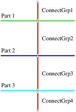
- When one processes Grid Point Forces internal forces and moments, the definition of grp1 and
grp2 may matter. Consider the example represented in Figure VII.4.1 in which Part 2 is a
sandwich panel modeled with shell elements. Then,
- If one calculates inserts margins of safety, loads should be extracted on elements
of sandwich panel at connection nodes because the inserts of sandwich panels
are loaded by connections of Groups “ConnectGrp2” and “ConnectGrp3”. This
means the grp1 should correspond to Part 2 and grp2 to either “ConnectGrp2” and
“ConnectGrp3”.
- On the other hand, if one calculates sliding between Part 1 and Part 2, only the loads
transmitted by elements of Group “ConnectGrp2” must be recovered. Then grp1
should correspond to Group “ConnectGrp2” and grp2 to Part2. Of course, this will
work only if the connections are modeled with elements (CBUSH, CBAR,...) and
not MPCs or rigid body elements (RBEs).
In many cases, grp1 and grp2 can be switched without consequences on the results. Then it is
generally less expensive to select grp1 corresponding to the Group containing the
connections.
Note however that when grp1 and grp2 are switched, the vector defining axial direction should
be reversed too!
All the operations are managed by subroutine “getConnectionLoads” of “ExtractionCriteria” VBA
module. This subroutine is called by each of the connection post-processing function. This is why the
six parameters (eight values) of these connection post-processing functions are always the
same.
VII.4.4.2.2 “getSlidingRF” function
This function calculates reserve factors for the sliding criterion with the following expression:
|
|
in which
is the friction coefficient between assembled elements and
is an
estimate of the minimum possible pretension of the bolt. Parameters specific to this function are:
- The factor of safety “FoS”. (Parameter 7 of the function.)
- The minimum estimated pretension of a connection “Pmin”. (Parameter 8 of the
function.)
- The friction coefficient “Cf”. (Parameter 9 of the function.)
- Two optional parameters containing the name of the GMSH file in which the envelope of
inverse reserve factors is saved, and the name of the Result by which it is referred to in
the GMSH file.
The function returns an Array of one line and four columns containing:
- The ID of the finite element entity to which minimum reserve factor corresponds. This is
the ID of an element for “BMFRC” extraction and a node ID otherwise.
- The corresponding axial force.
- The corresponding shear force.
- The minimum reserve factor.
VII.4.4.2.3 “getGappingRF” function
This function calculates reserve factors for the gapping criterion with the following expression:
|
|
in which is
a parameter that allows to take into account the prying effect related to the bending moment in the connection
and is
an estimate of the minimum possible pretension of the bolt. Parameters specific to this function are:
- The factor of safety “FoS”. (Parameter 7 of the function.)
- The minimum estimated pretension of a connection “Pmin”. (Parameter 8 of the
function.)
- The friction coefficient “Radius”. (Parameter 9 of the function.)
- Two optional parameters containing the name of the GMSH file in which the envelope of
inverse reserve factors is saved, and the name of the Result by which it is referred to in
the GMSH file.
The function returns an Array of one line and four columns containing:
- The ID of the finite element entity to which minimum reserve factor corresponds. This is
the ID of an element for “BMFRC” extraction and a node ID otherwise.
- The corresponding axial force.
- The corresponding bending moment.
- The minimum reserve factor.
VII.4.4.2.4 “getInsertRF” function
This function calculates reserve factors for the insert criterion with the following expression:
|
|
In which “PSS” is the axial allowable of the insert and “QSS” is its shear allowable. Parameters
specific to this function are:
- The factor of safety “FoS”. (Parameter 7 of the function.)
- The insert axial allowable “PSS”. (Parameter 8 of the function.)
- The insert shear allowable “QSS”. (Parameter 9 of the function.)
- Two optional parameters containing the name of the GMSH file in which the envelope of
inverse reserve factors is saved, and the name of the Result by which it is referred to in
the GMSH file.
The function returns an Array of one line and four columns containing:
- The ID of the finite element entity to which minimum reserve factor corresponds. This is
the ID of an element for “BMFRC” extraction and a node ID otherwise.
- The corresponding axial force.
- The corresponding shear force.
- The minimum reserve factor.
VII.4.4.2.5 “getShearBearingRF” function
This function calculates reserve factors for the shear-bearing failure mode with the following
expression:
|
|
in which
is the shear bearing allowable. Parameters specific to this function are:
- The factor of safety “FoS”. (Parameter 7 of the function.)
- The shear-bearing allowable “ShrAll”. (Parameter 8 of the function.)
- Two optional parameters containing the name of the GMSH file in which the envelope of
inverse reserve factors is saved, and the name of the Result by which it is referred to in
the GMSH file.
The function returns an Array of one line and three columns containing:
- The ID of the finite element entity to which minimum reserve factor corresponds. This is
the ID of an element for “BMFRC” extraction and a node ID otherwise.
- The corresponding shear force.
- The minimum reserve factor.
VII.4.4.2.6 “getPullThroughRF” function
This function calculates reserve factors for the pull-through failure mode with the following
expression:
|
|
in which
is the pull-through tensile allowable. Parameters specific to this function are:
- The factor of safety “FoS”. (Parameter 7 of the function.)
- The pull-through allowable “PullAll”. (Parameter 8 of the function.)
- Two optional parameters containing the name of the GMSH file in which the envelope of
inverse reserve factors is saved, and the name of the Result by which it is referred to in
the GMSH file.
The function returns an Array of one line and three columns containing:
- The ID of the finite element entity to which minimum reserve factor corresponds. This is
the ID of an element for “BMFRC” extraction and a node ID otherwise.
- The corresponding axial force.
- The minimum reserve factor.