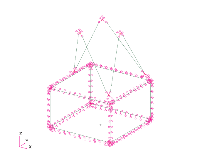
Figure IV.1.1: Overall view of the satellite’s finite element model.
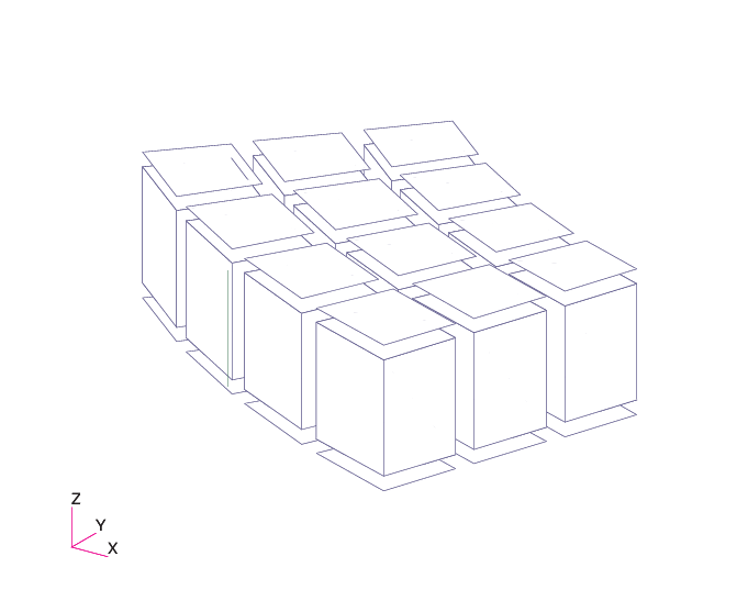
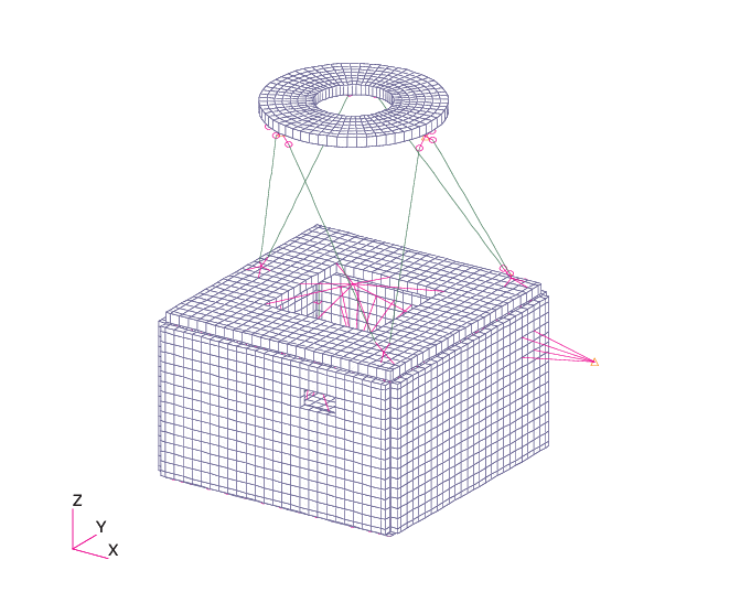
An overall view of the satellite’s FE model is presented in Figure IV.1.1. Basically, the structure is composed of an hexahedral lower box and of an upper panel supported by six struts. The hexahedral lower box is made of six sandwich panels connected on 12 metallic bars along their edges. The metallic bars are connected to eight corner nodes. A view of the lower box metallic frame, without the sandwich panels is given in Figure IV.1.2. The corner nodes, and the connections of sandwich panels are modeled with RBE2 elements. However, for thermo-elastic calculations these RBE2 elements are replaced by very stiff CBAR elements.
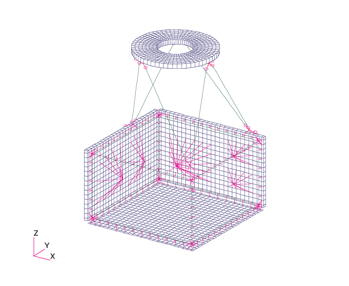
The sandwich panels are generally modeled with volumic elements for the honeycomb and surfacic elements for the skins (Figure IV.1.3). A surfacic modeling of a sandwich panel with layered (PCOMPG) element properties has been chosen for only one of the panels: the bottom panel.
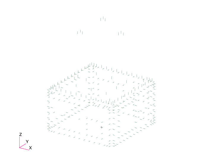
To ensure a good transfer of loads to the panels, in particular of the bending moments at connections, small traversing elements have been introduced in the panels modeled with 3D elements. Those elements represent the inserts and connect the two skins. A global view of all the traversing elements is given in Figure IV.1.4.
The struts are modeled with CBAR elements. The struts are connected to the upper panel and to the box +Z panel through metallic fittings modeled with CONM2 and RBE2 elements. (The RBE2 elements are replaced by very stiff CBAR elements for thermo-elastic calculations). The connections of struts to the fittings are ball-bearing connections (only translational degrees of freedom are transmitted, except on the lower side, where the rotation of each strut around its axis is blocked).
The equipments connected to the sandwich panels are modeled with CONM2 and RBE2 elements. (The RBE2 elements are replaced by very stiff CBAR elements for thermo-elastic calculations). A view of some equipments is presented in Figure IV.1.5. On some panels small equipments are modeled by adding a NSM (non-structural mass) to PSHELL properties.