FeResPost Web Site                     FeResPost Online User Manual

III.1.2.1 General Results

The correspondence between the Nastran output requests and the DMAP data blocks written in the “op2” file is given in Tables III.1.7 to III.1.16. Note that in all the examples presented in Part IV, the results are printed in the “op2” file with “SORT1” option. This means that no test has been done with “SORT2” option.


Table III.1.7: Correspondence between the Nastran output cards and the “op2” result data blocks. (Displacements read from OUG data blocks.)


Nastran “op2” Generated
StatementData Block Result


DISPL OUG “Displacements, Translational” “Displacements, Rotational” “Displacements, Scalar”


VELO OUG “Velocities, Translational” “Velocities, Rotational” “Velocities, Scalar”


ACCEL OUG “Accelerations, Translational” “Accelerations, Rotational” “Accelerations, Scalar”


Table III.1.8: Correspondence between the Nastran output cards and the “op2” result data blocks. (Applied loads read from OPG data blocks.)


Nastran “op2” Generated
Statement Data Block Result


OLOAD (2) OPG “Applied Loads, Forces” “Applied Loads, Moments”


Table III.1.9: Correspondence between the Nastran output cards and the “op2” result data blocks. (MPC and SPC forces read from OQG data blocks.)


Nastran “op2” Generated
Statement Data Block Result


MPCFORCES (2) OPG “MPC Forces, Forces” “MPC Forces, Moments” “MPC Forces, Scalar”


SPCFORCES (2) OPG “SPC Forces, Forces” “SPC Forces, Moments” “SPC Forces, Scalar”


Table III.1.10: Correspondence between the Nastran output cards and the “op2” result data blocks. (Grid point forces read from OGF data blocks.)


Nastran “op2” Generated
Statement Data Block Result


GPFORCES (2) OGF “Grid Point Forces, Internal Forces” “Grid Point Forces, Internal Moments” “Grid Point Forces, MPC Forces” (2) “Grid Point Forces, MPC Moments” (2) “Grid Point Forces, MPC Internal Forces” (3) “Grid Point Forces, MPC Internal Moments” (3) “Grid Point Forces, SPC Forces” (2) “Grid Point Forces, SPC Moments” (2) “Grid Point Forces, Applied Forces” (2) “Grid Point Forces, Applied Moments” (2)


Table III.1.11: Correspondence between the Nastran output cards and the “op2” result data blocks. (Strains read from OES data blocks and corresponding to “STRAIN” output requests..)


Nastran “op2” Generated
StatementData Block Result


STRAIN OES “Strain Tensor” (4, 2) “Beam Axial Strain for Axial Loads” “Beam Axial Strain for Bending Loads” “Beam Axial Strain for Total Loads” (8) “Beam Shear Strain for Torsion Loads” “Beam Deformations” (14) “Beam Velocities” (14) “Beam Stations” (17) “Gap Forces” (15) “Gap Deformations” (15) “Gap Slips” (15) “Spring Scalar Strain” “Bush Forces Strain Tensor” (12 and 13) “Bush Moments Strain Tensor” (12 and 13) “Bush Plastic Strain” (12 and 13) “Curvature Tensor” (4, 7) “Shear Panel Strain, Max” “Shear Panel Strain, Average”


Table III.1.12: Correspondence between the Nastran output cards and the “op2” result data blocks. (Stresses read from OES data blocks and corresponding to “STRESS” output requests.)


Nastran “op2” Generated
StatementData Block Result


STRESS OES “Stress Tensor” (1 in section III.1.2.2) “Beam Axial Stress for Axial Loads” “Beam Axial Stress for Bending Loads” “Beam Axial Stress for Total Loads” (8) “Beam Shear Stress for Torsion Loads” “Beam Forces” (12 and 13) “Beam Moments” (12 and 13) “Beam Deformations” (14) “Beam Velocities” (14) “Beam Stations” (17) “Gap Forces” (15) “Gap Deformations” (15) “Gap Slips” (15) “Spring Scalar Stress” “Bush Forces Stress Tensor” (12 and 13) “Bush Moments Stress Tensor” (12 and 13) “Bush Stress, Axial” (14) “Bush Strain, Axial” (14) “Bush Plastic Strain” (14) “Shear Panel Stress, Max” “Shear Panel Stress, Average”


Table III.1.13: Correspondence between the Nastran output cards and the “op2” result data blocks. (Nonlinear stresses read from OES data blocks and corresponding to “NLSTRESS” or other output requests (18).)


Nastran “op2” Generated
Statement Data Block Result


NLSTRESS OES “Nonlinear Stress Tensor” (5) “Nonlinear Strain Tensor” (5) “Nonlinear Effective Plastic Strain” (5) “Nonlinear Effective Creep Strain” (5) “Nonlinear Spring Scalar Strain” “Nonlinear Spring Scalar Stress” “Nonlinear Beam Axial Strain for Axial Loads” “Nonlinear Beam Axial Stress for Axial Loads” “Nonlinear Beam Axial Strain for Total Loads” “Nonlinear Beam Axial Stress for Total Loads” “Nonlinear Beam Forces” “Nonlinear Beam Moments” “Beam Stations” (17) “Nonlinear Bush Forces Stress Tensor” (12 and 13) “Nonlinear Bush Moments Stress Tensor” (12 and 13) “Nonlinear Bush Forces Strain Tensor” (12 and 13) “Nonlinear Bush Moments Strain Tensor” (12 and 13) “Nonlinear Gap Forces” (15) “Nonlinear Gap Deformations” (15) “Nonlinear Gap Slips” (15)


Table III.1.14: Correspondence between the Nastran output cards and the “op2” result data blocks. (Element forces read from OEF data blocks or other “FORCE” output.)


Nastran “op2” Generated
Statement Data Block Result


FORCE (1, 14) OEF “Shell Forces” “Shell Moments” (6) _______________________________________________ “Beam Forces” (9, 10,11) “Beam Moments” (9, 10,11) “Beam Warping Torque” “Beam Deformations” “Beam Velocities” “Beam Stations” (17) “Gap Forces” (15) “Gap Deformations” (15) “Gap Slips” (15) “Spring Scalar Forces” “Bush Plastic Strain”


Table III.1.15: Correspondence between the Nastran output cards and the “op2” result data blocks. (Element forces read from OEE data blocks or “ESE”, “EKE” and “EDE” output.)


Nastran “op2” Generated
StatementData Block Result


ESE OEE “Element Strain Energy” “Element Strain Energy (Density)” “Element Strain Energy (Percent of Total)”


EKE OEE “Element Kinetic Energy” “Element Kinetic Energy (Density)” “Element Kinetic Energy (Percent of Total)”


EDE OEE “Element Energy Loss” “Element Energy Loss (Density)” “Element Energy Loss (Percent of Total)”


Table III.1.16: Nastran Results for thermal calculations.


Nastran “op2” Generated
Statement Data Block Result


TEMPERATURE OUG “Temperature”


FLUX OEF “Temperature Gradient”
FLUX OEF “Conductive Heat Flux”


One can make a few remarks about the information given in Tables III.1.7 to III.1.16:

1.
The Nastran “CELASi” and “CDAMPi” elements produce scalar forces or moments that are stored in “Beam Scalar Forces” Results.
2.
“Applied Loads” are available both with the “OLOAD” and “GPFORCE” Nastran statements. A similar remark can be done for “MPC Forces” and “SPC Forces”.
3.
When the option “RIGID=LAGR” is activated, the contributions of rigid body elements and MPCs are included in “Grid Point Forces, MPC Forces” and “Grid Point Forces, MPC Moments” and not in “Grid Point Forces, Internal Forces” and “Grid Point Forces, Internal Moments”:
4.
The shear components of strain tensor output by Nastran are the angular deformations: γij = 2ϵij. When these results are imported in a NastranDb, the corresponding components are divided by two in such a way that a “physical” tensor is stored into the NastranDb. The same remark applies for the non-diagonal components of the curvature tensor (shell elements).

The “STRAIN” Nastran output statement with “FIBER” option outputs the strain tensor at Z1 and Z2, but do not produce the curvature tensor.

5.
The Nonlinear stresses and strains are available for CHEXA, CPENTA, CTETRA, CQUAD4 and CTRIA3 elements. Plastic deformation results are produced for non-linear results only.
6.
When shell bending moments are imported from Nastran finite element results, the sign of each component is changed. This has been done to ensure that a positive component of the bending moment results in a positive value of the corresponding stress tensor component on the upper face of the shell. In other words, a positive bending corresponds to tension stress in shell upper face. (See equation II.1.31 for the definition of bending moments tensor components.)
7.
When Nastran shell curvature Results are imported, two modifications are brought to the components:

This is done because FeResPost considers that positive curvature components correponds to positive strain components in upper face of the shell, and negative components in lower face of the shell. (See equation II.1.32 for the definition of curvature tensor components.)

8.
“Axial Strain” or “Axial Stress” for “Total Loads” and CBAR elements are produced by combined axial loads to bending loads. This has been done to harmonize CBAR Results with CBEAM Results. For CBEAM Results, Stresses or Strains are recovered on the extremities only.
9.
Nastran “BEAM” type elements (CBAR, CBEAM, CBEND,...) do not output vectorial or tensorial forces or moments. Instead, the different components are expressed in different coordinate systems (axial, plane 1 and plane 2). When importing these Results, a conversion into tensorial format is done as follows:
F = FxxFxyFxz Fxy 0 0 Fxz 0 0 = FaxialV 1V 2 V 1 0 0 V 2 0 0 ,
M = MxxMxyMxz Mxy 0 0 Mxz 0 0 = Mtorsion - M2M1 - M2 0 0 M1 0 0 .
10.
Nastran CBUSH elements produce forces and moments corresponding to the loads applied by Grid B of the element to Grid A. By analogy with the what is done for “BEAM” type of elements, one produces “Beam Forces” and “Beam Moments” filled as follows:
F = FxxFxyFxz Fxy 0 0 Fxz 0 0 = FxFyFz Fy 0 0 Fz 0 0 ,
M = MxxMxyMxz Mxy 0 0 Mxz 0 0 = MxMyMz My 0 0 Mz 0 0 .

The choice of considering bush forces and moments as beams is questionable, and we justify this choice as follows:
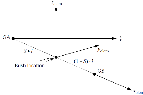
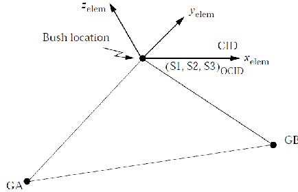
CBUSH elements are often used in the modeling of connections. Whatever the type of coordinate system definition, is is always possible to obtain vectorial forces and moments by a contracted multiplication of the vectorial result with a unit vector:

f = FxxFxyFxz Fxy 0 0 Fxz 0 0 1 0 0 = Fxx Fxy Fxz ,
m = MxxMxyMxz Mxy 0 0 Mxz 0 0 1 0 0 = Mxx Mxy Mxz .

This is generally the first operation performed when CBUSH loads are used for the sizing of connections. This also works when connection forces are extracted from CBEAM or CBAR elements.


PICT
(a)
PICT
(b)

Figure III.1.1: CBUSH element axes definition. (Pictures extracted from [Sof04b].)

11.
For CBAR elements, “Beam Forces” are always produced at the center of elements, and “Beam Moments” at the two end nodes. For CBEAM elements, “Beam Forces” and “Beam Moments” can be requested at different stations long the element. A minimum is then the production of outputs at the two ends of the element; Therefore, “Beam Forces” are output at element end nodes, as a minimum. But generally, no “Beam Forces” are output at element centers.
12.
Bush result types for OEF and OES outputs depend on the kind of BUSH elements to which they correspond:

The element forces and moments are stored in “Beam Forces” and “Beam Moments” tensorial Results.

13.
The result types generated for CFAST elements are the same as for CBUSH elements.

Note that FeResPost cannot determine the CFAST element coordinate system when grids A and B are coincident. This may cause problems when transformation of reference coordinate systems are required. (This is the case when gmsh outputs of results are requested.) Note also that Patran also seems to experience some difficulties to calculate CFAST element axes.

14.
Nastran “CBUSH1D” elements produce scalar results in OEF and OES blocks. By this we means that each type of result has only one single component. However, the scalar force is stored in “Beam Forces” tensorial result. Most components of the tensor are zero:
F = Fxx00 0 00 0 0 0 .

No bending moments are produced by “CBUSH1D” elements.

15.
Nastran “CGAP” elements produces various results. These Results are read from OES or OEF data blocks. These Results are tensorial and:
16.
Various Nastran elements refer scalar points instead of grids. Nevertheless, Nastran considers the scalar point as a kind of element rather than as a kind of grid. This is, in our opinion, an unfortunate choice! FeResPost considers SPOINT and EPOINT objects as a peculiar type of GRID. This has implications for the definition of keys when importing Results with from Nastran op2 files. One hopes that this will not lead to problems!
17.
The “Beam Stations” scalar result is produced when stresses, strains or forces are read for CBEAM or CBAR elements:
18.
“Nonlinear” outputs may result from various output requests as “NLSTRESS”, “STRESS”, “STRAIN”, “FORCE”... The “Nonlinear” character of Results is more related to the type of Nastran solution than to the output request. For example, Nastran SOL 106 or SOL 400 analyses are likely to produce “Nonlinear” outputs.